
Why pressure matters
Most drip products are rated for somewhere between 10 and 25 PSI. Feed them 40 PSI from a typical suburban hose bib and one of two things happens: emitters pop apart, or compression fittings creep off the tubing under continuous load and you find a quiet flood later.
A three-part inline assembly solves this: backflow preventer, filter, regulator. It takes fifteen minutes to build, costs little compared with the mess it avoids, and makes the rest of the bed behave predictably.
Parts list
- Backflow preventer with 3/4 inch female hose thread in, 3/4 inch male out
- Y-strainer filter, 150-mesh
- Pressure regulator, 25 PSI
- Compression adapter, 3/4 inch MHT to 1/2 inch compression
- 1/2-inch polyethylene tubing
- End cap or figure-8 clamp
- PTFE tape
- Optional: inline pressure gauge
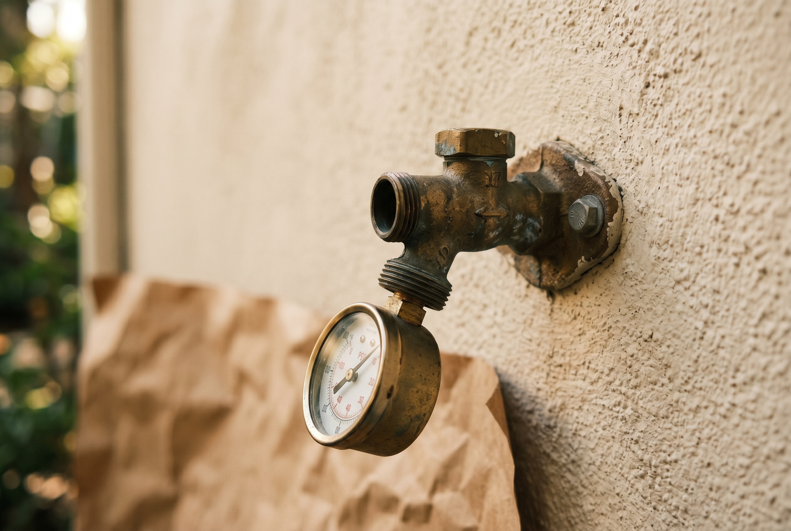
01 — Measure your hose-bib pressure
Before you buy a regulator, confirm what you are regulating down from. Screw a pressure gauge onto the hose bib and turn the water on. Wait for the needle to stabilize.
Most suburban bibs read 40 to 80 PSI. If yours reads below 25, you may not need a regulator at all. If it reads well above 80, address the house-side pressure problem instead of expecting a small drip regulator to absorb it forever.
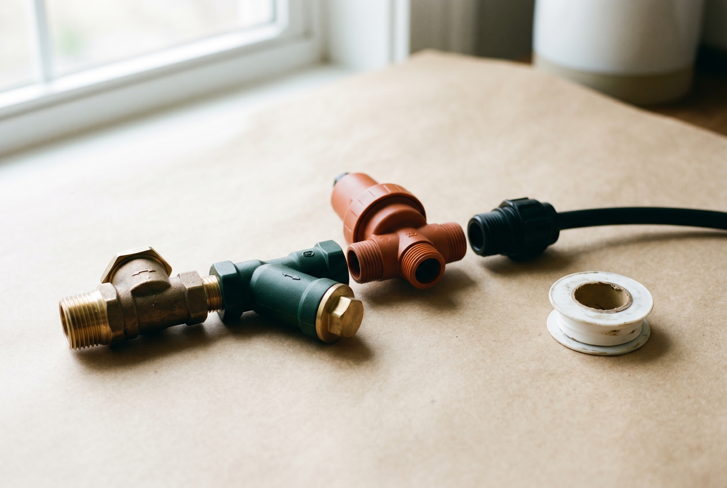
02 — Build the header assembly off the bench
Assemble the four pieces, backflow preventer, filter, regulator, and compression adapter, on the bench rather than on the bib. It is easier to align threads when the assembly is flat.
Flow order stays the same every time: bib -> backflow preventer -> filter -> regulator -> compression adapter -> tubing.
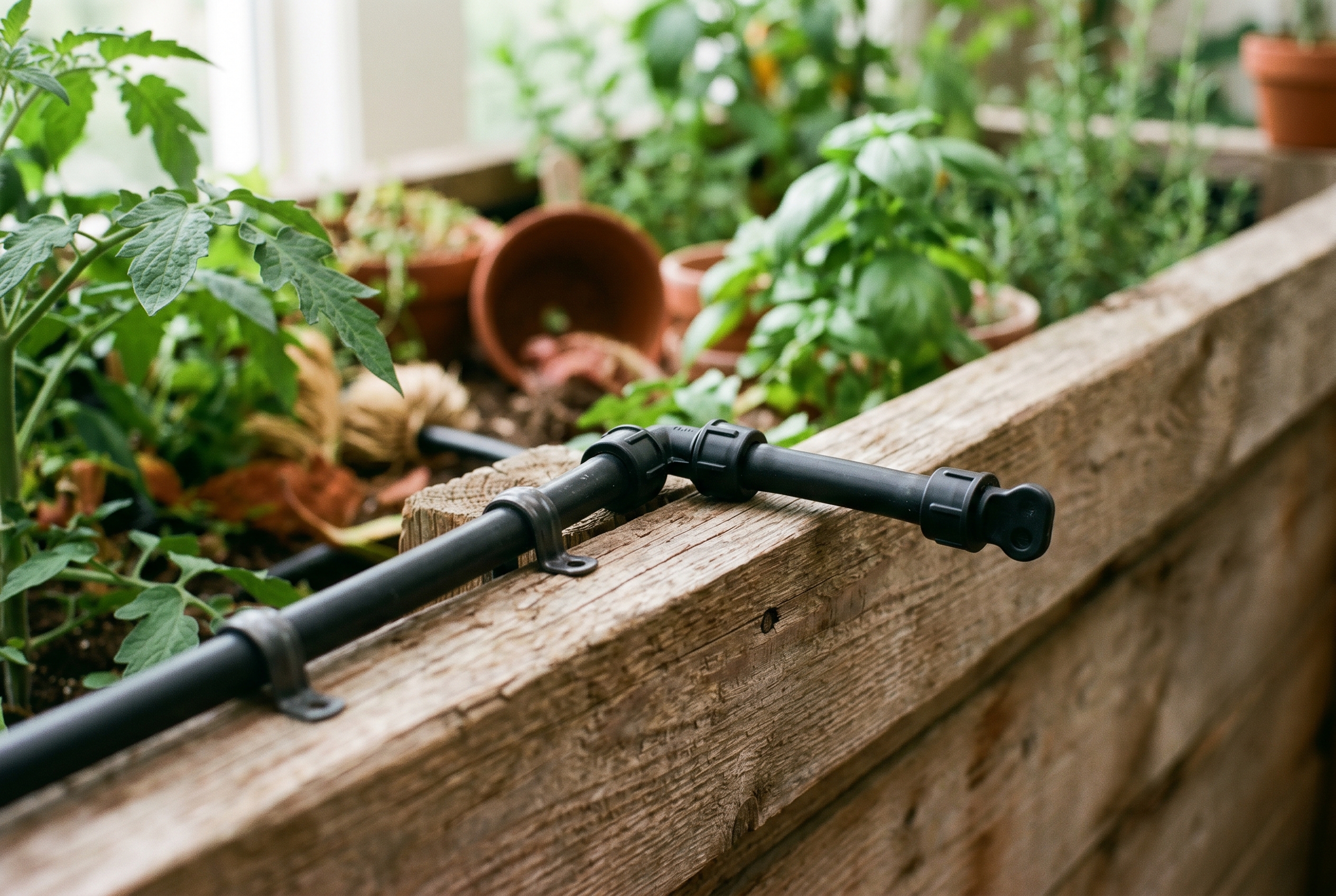
03 — Run the 1/2-inch main line along the bed
The 1/2-inch polyethylene tubing is the main carrier. Run it along the long side of the raised bed, just below the top rail where it is partly shaded from UV. Terminate the far end with an end cap or figure-8 clamp so seasonal draining stays easy.
For multiple beds in series, keep the main line simple and tee off cleanly rather than improvising a mess of reducers at every corner.
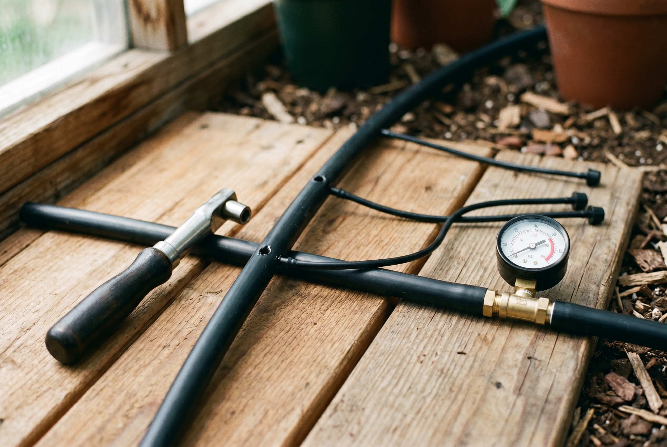
04 — Punch in emitters and pressure-check at the far end
Use a proper emitter punch to create each port. Do not use a drill or knife. Those cuts end up oval and leak around the barb.
During commissioning, a gauge at the far end should read close to the regulator rating under flow. If it is much lower, inspect the filter first before blaming every downstream fitting.
Winterizing
At the end of the season, shut the bib, remove the regulator assembly, drain the tubing, and store the regulator indoors. The tubing itself can usually winter in place.